dendritic solidification, eutectics, peritectics,....
-
Manoj540
- Posts: 9
- Joined: Tue Jul 12, 2016 7:48 am
- anti_bot: 333
Post
by Manoj540 » Tue Jul 12, 2016 8:42 am
Hello
I am totally new to the Micress and am trying to find out to grow dendrites of Fe -C-Cr alloy from liquid to BCC . But I got a problem after maximum phase1(BCC) fraction again its decreasing and dendrites are forming . I don't why it is happening.
I tried for cooling rate of (-50 K/s) and (-1k/s) in case of cooling rate of 50k/s temperature keeps on decreasing but in case of 1k/s it decrease and again it increases
you can find my attachment also of results.
- manoj16.in
- input file
- (21.58 KiB) Downloaded 250 times
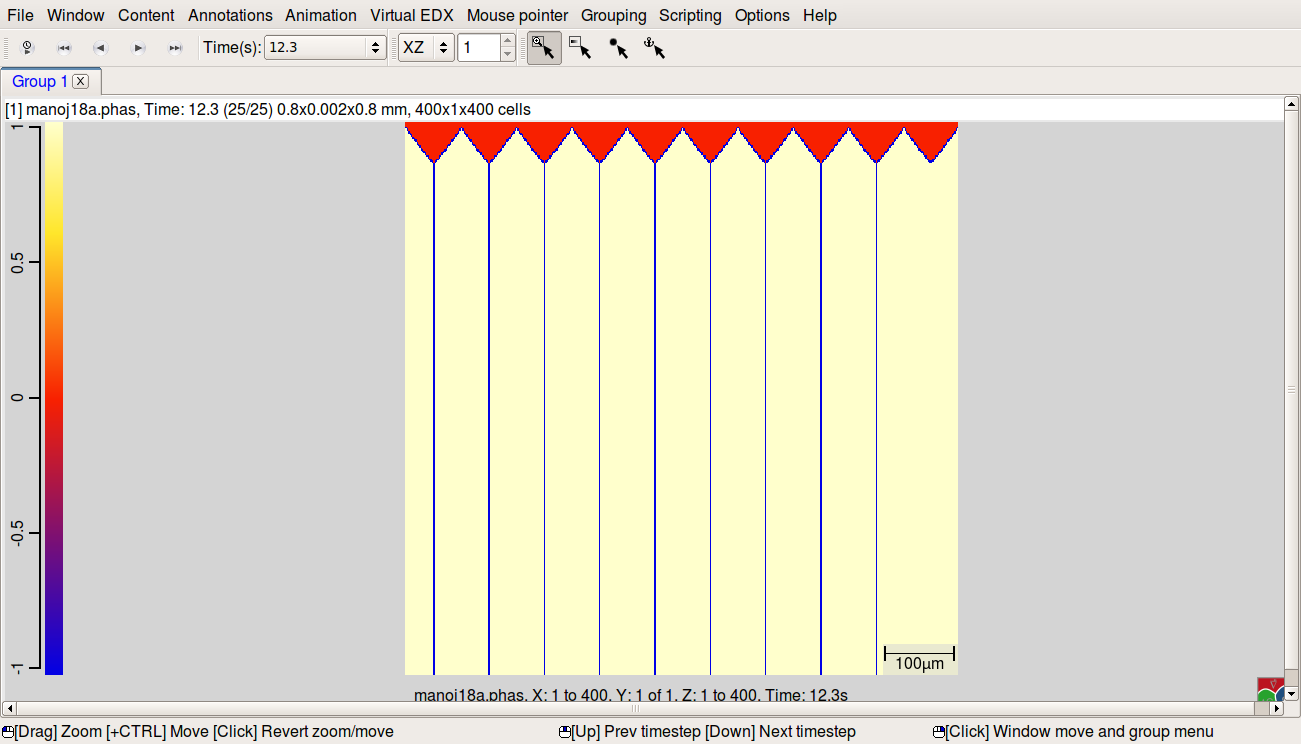
- this was happend till 1688 K
- frist.png (54.24 KiB) Viewed 4693 times
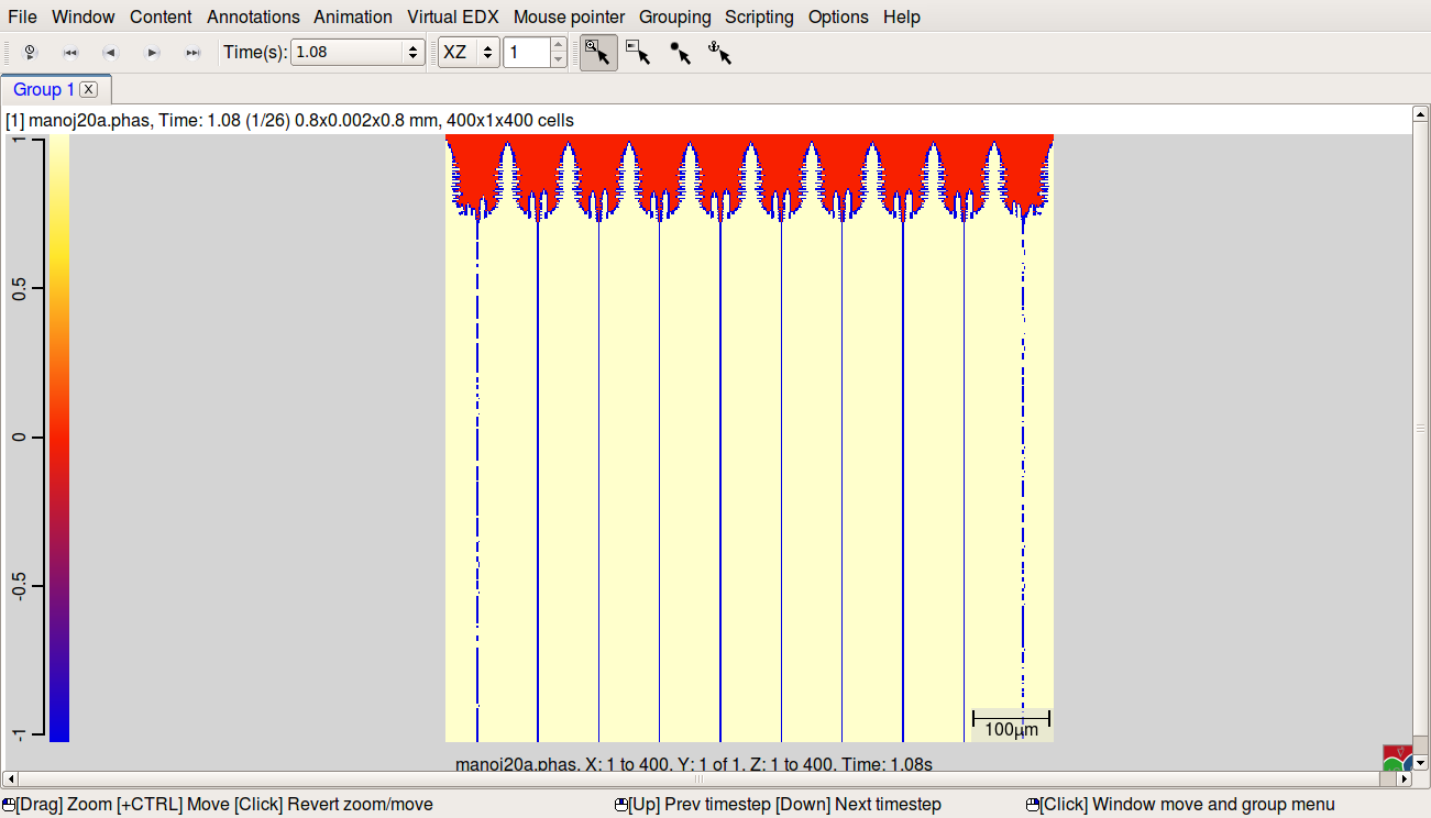
- after 1688k liq gets shrinkage
- next & liq shrikage .png (56.61 KiB) Viewed 4693 times
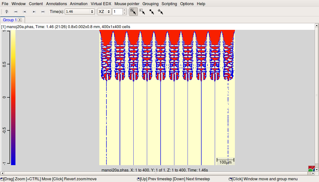
- liq shrinkage and dendrites growing
- liq Shrinlage and dendrites growing.png (67.65 KiB) Viewed 4693 times
-
Bernd
- Posts: 1506
- Joined: Mon Jun 23, 2008 9:29 pm
Post
by Bernd » Tue Jul 12, 2016 6:53 pm
Dear Manoj540,
Welcome to the MICRESS Forum.
It seems that you re-used an existing input file without fully understanding all the features which are used there.
The driving file which you appended uses the "moving_frame" option which allows the simulation domain to follow the dendrite tips in directional solidification when they approach the top boundary up to a specified distance. This explains why the bottom temperature (which is written to several output files) does not reflect the cooling rate any more once the moving frame is in action.
The top boundary condition for the concentration field is chosen as fixed which makes sense for respecting a fixed far-field in directional solidification. By use of an additional "1d_far_field" with 50 cells at the top, this boundary condition is shifted to the top of this one-dimensional field allowing us for taking into account long-range diffusion, which - from a certain distance above the dendrite front - can be approximated as 1d. This 1d_far_field option includes the possibility to also partially perform diffusion inside the simulation domain in 1D, as long as the dendritic front is still close to the bottom. The main purpose of this feature is to speed up simulation during this initial period. A distance must be provided from where above the highest dendrite diffusion is done only in 1D, which must be at least the length until where lateral concentration gradients reach upwards (length of diffusion field around dendrites).
This sounds more complicated than it is. In practically all cases, the moving frame distance (input in section "Boundary Conditions") and the distance for the 1D-solution inside the simulation domain (in section "Initial concentration") should be identical. Then, when the moving frame is in action, the region between the dendrite tips and the top boundary condition (20 µm in your case) is solved in 2D(3D), followed by the 1D prolongation outside the domain.
Essentially, there are two major things which you overlooked:
- Chosing a moving frame distance of only 2µm brings the dendrite tips very close to the top boundary. There is still a prolongation of 100 µm outside the domain, but the connection between the 1d and 2D(3D) regions corresponds to an infinite lateral diffusion! This creates strong artifacts on the dendrite tips and can easily be avoided by setting the moving frame distance also to 20 µm (please check whether this is sufficient in your case, especially for the lower cooling rate).
- The fixed boundary condition for the concentration field requires the input of the concentration values for this boundary which should be the same as your alloy composition (far-field composition of liquid). You probably forgot to change these values which makes your simulation changing gradually to a different alloy.
Best wishes and good luck
Bernd
-
Manoj540
- Posts: 9
- Joined: Tue Jul 12, 2016 7:48 am
- anti_bot: 333
Post
by Manoj540 » Wed Jul 13, 2016 9:12 am
Dear Bernd
Thanks for helping to find out the problem.
Now I modified my input file by removing the 'moving_frame' and '1_d_far_field'. The problem is that there is no secondary dendrite growing is happening.
please can you help me out from this problem.
I am thinking this is because of my anisotropy values or grid size
you can find input file attachment.
Thank you
-
Bernd
- Posts: 1506
- Joined: Mon Jun 23, 2008 9:29 pm
Post
by Bernd » Wed Jul 13, 2016 4:28 pm
Dear Manoj540,
I am wondering why you do not have defined a temperature gradient. Which type of process you want to simulate? Without gradient, there will be no stationary growth process...
Apart from that, the formation of side branches strongly depends on the correct choice of the interface mobility. Please attach screenshots of your results including the .conc and .driv output.
Bernd
-
Manoj540
- Posts: 9
- Joined: Tue Jul 12, 2016 7:48 am
- anti_bot: 333
Post
by Manoj540 » Thu Jul 14, 2016 7:55 am
Dear Bernd
I am trying to do with temperature gradient and without.
In my input file I mentioned the output of .driv is no_out_driv_force
I will modify my input file with out.driv and with temp gradient and high cooling rates
And I also found that .conc there is no dendrite grow can you help me out from this problem
Here are the attachments of .conc and .phas of the input file which I had attached in previous post
Thanking you
Manoj
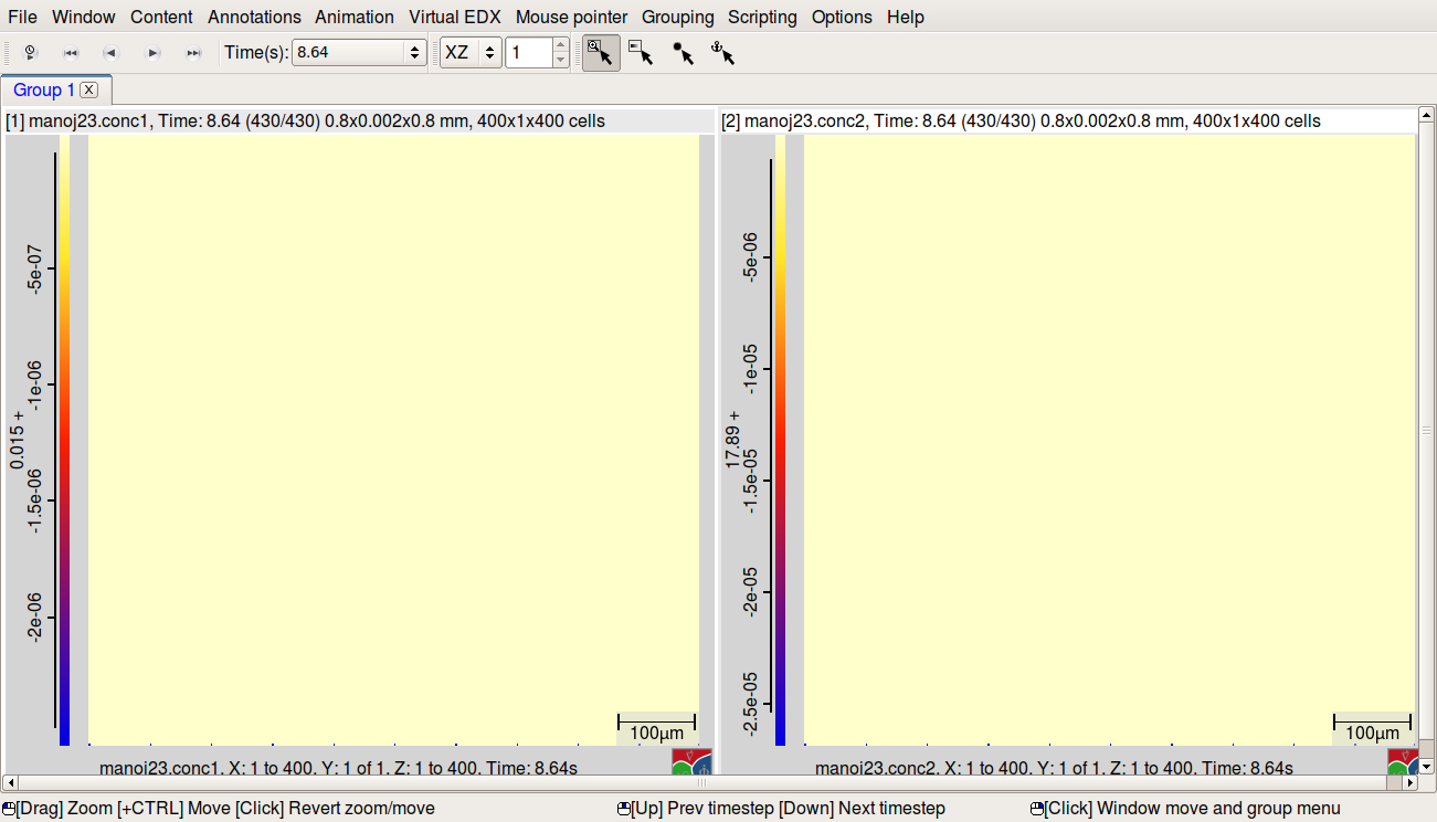
- .conc
- coc1= c and con2 = Cr.png (74.59 KiB) Viewed 4680 times
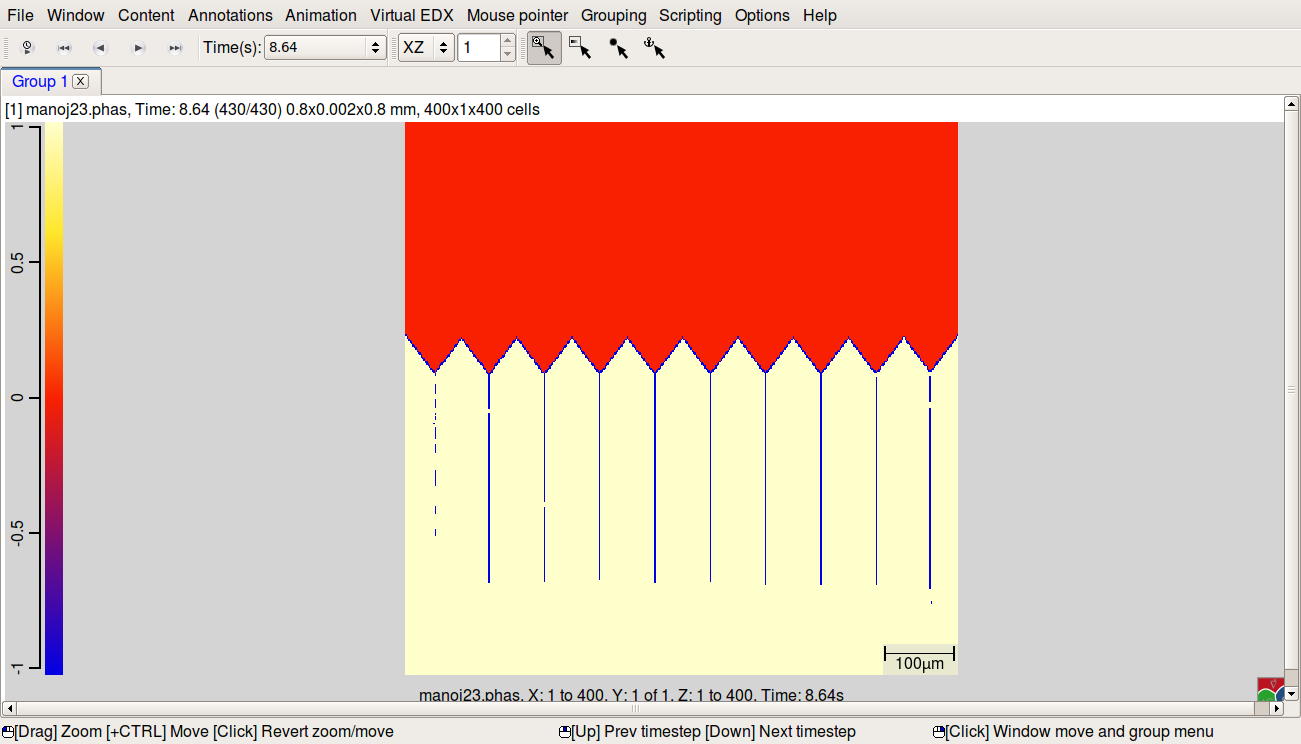
- .phas
- phase.png (55.29 KiB) Viewed 4680 times
-
Bernd
- Posts: 1506
- Joined: Mon Jun 23, 2008 9:29 pm
Post
by Bernd » Thu Jul 14, 2016 4:01 pm
Hi Manoj540,
this is very strange. Obviously, you do not have any concentration changes in the simulation domain...
This means that either the diffusion coefficients are 0 (no mobility data in .ges5 file?, please check in .TabD and in .diff) or that there is something wrong with the thermodynamic data themselves. Please attach the .log file (which contains the linearisation data for the initial equilibrium) and (if available) the screen output.
Bernd
-
Manoj540
- Posts: 9
- Joined: Tue Jul 12, 2016 7:48 am
- anti_bot: 333
Post
by Manoj540 » Thu Jul 14, 2016 5:08 pm
Hello Bernd
I checked my .TabD and .diff there diffusion coefficients are shown NAN.
I have attached .log file
-
Bernd
- Posts: 1506
- Joined: Mon Jun 23, 2008 9:29 pm
Post
by Bernd » Thu Jul 14, 2016 5:19 pm
The linearisation parameter seem OK.
Did you append mobility data to the .ges5 file? Are they compatible with the current MICRESS version (which Thermo-Calc version was used?). You may also have used a wrong mobility database which is not compatible to the thermodynamic database.
If you created the .ges5 file by hand, please try again, an error may have occurred. If you used a script for that, please show the script to check for errors.
Bernd
-
Manoj540
- Posts: 9
- Joined: Tue Jul 12, 2016 7:48 am
- anti_bot: 333
Post
by Manoj540 » Thu Jul 14, 2016 5:42 pm
Hello Bernd
I am Using Micress 6.2 and Thermo- Calc 2015b
Yes I append the mobility data .ges5 file
Yes they compatible with the current MICRESS version
I will try again by creating .ges5 file.
-
Manoj540
- Posts: 9
- Joined: Tue Jul 12, 2016 7:48 am
- anti_bot: 333
Post
by Manoj540 » Fri Jul 15, 2016 11:57 am
Hello Bernd
I am struggling to get dendrite for the ternary composition As I mentioned above I have created new ges5 file
I have observed that in .TabD all the values are zero and in .diff Diff conc are there
and there is no dentrite grow in .con and .phas
Input file attached here
- manoj26.in
- input file
- (20.55 KiB) Downloaded 267 times
Thanking you
Manoj